Getting Started with Basic Modeler
This guide will help you get familiar with the Basic Modeler application and script syntax. To get started, load the free Basic Modeler web application.
When you first fire up the app, you will be presented with an empty project.
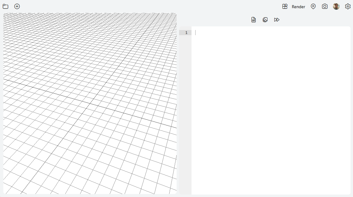
On the left side of the screen is the rendering preview area, and on the right side is the code editor. Basic Models are designed with a scripting language. Enter the following code into the editor to create your first model, and then click on the Render button on the top toolbar.
// a basic cube
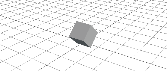
box(1, 1, 1);
The output will look like the following, just a plain gray cube.
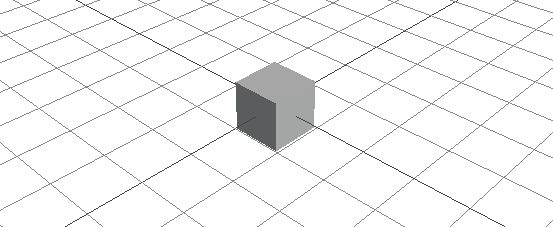
Let's look at what the code is doing here. The first line in the code begins with two slashes, which marks that line as a comment. Comments are useful in Basic Modeler scripts, just as they are in programming, so it's good to get into the habit of using them!
The next line says that we want to create a box object with a width, height, and depth of 1. The syntax for a box is: box(width, height, depth). You can play around with the variables by changing the numbers to see what it does. For example, doing this:
// a basic cube
box(3, 2, 1);
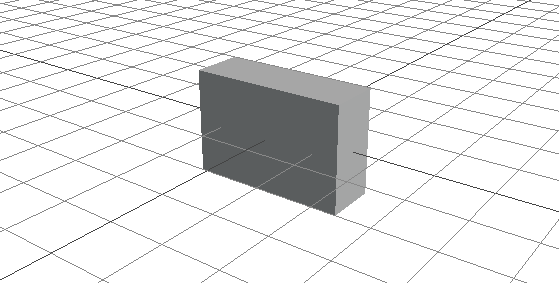
Will yield a box that is 3 units wide, 2 units high, and 1 unit deep.
The box object supports other properties as well, and you can read up on the full box object documentation here.
Let's go back to our cube and change the code a bit. Modify your script to look like this:
// a basic cube
$box = box(1, 1, 1);
In front of the box object declaration, we have added $box =. What this did was assign our little cube to a variable named box, which we can then reference later in the script. When assigning or using a variable, we always start variable names using the $ symbol. Further modify the code to look like this:
// a basic cube
$box = box(1, 1, 1);
$box > position(0, 0.5, 0);
Here is what our model looks like now:
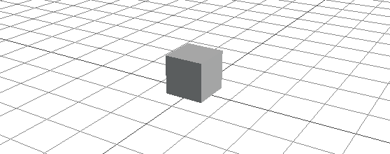
In our second line of code, we first "activated" our box variable, and then modified it's position using the position command. Objects in Basic Modeler are originated at their center, and since our cube is a size of 1 on all sides, we needed to move it up by half (0.5) in order to make it sit neatly on the top of the grid. The position command takes X, Y, and Z as it's parameters, and since we wanted to move the box up, we had to adjust its Y position.
Command modifiers can also be chained on a single line. Suppose we also wanted to rotate the cube slightly. Modify the code again like this:
// a basic cube
$box = box(1, 1, 1);
$box > position(0, 0.5, 0) > rotate(45, 0, 0);
We now get the following result:
The rotate command will rotate an object on its X, Y, and Z axis, specified in degrees. Note that you do not need to one-line commands like this, the following code will produce the exact same results:
// a basic cube
$box = box(1, 1, 1);
$box > position(0, 0.5, 0);
$box > rotate(45, 0, 0);
Sometimes you might want to perform transform operations on multiple objects at the same time. For this purpose, Basic Modeler supports grouping of objects together. Let's start off by adding a second object to the scene, a cylinder. Adjust your code to look like the following:
// a cube and a cylinder
$box = box(1, 1, 1) > position(0, 0.5, 0);
$pole = cylinder(0.5, 0.5, 2, 8) > position(0, 2, 0);
Which will give us the following output:
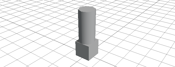
You may have noticed a new trick here as well. You can in-line transform commands on the same line of code you use to create a new object. Here we adjusted the position of both the box and the cylinder on the same line that we created them on. We also assigned the new cylinder to the pole variable. As with the box, there are more parameters available for the cylinder, which you can read up on here.
There are two different ways to create an object group in Basic Modeler. The first is to create a new object of the type empty. An empty is a special type of object that exists only to hold other objects. Modify your code to look like this:
// a cube and a cylinder
$box = box(1, 1, 1) > position(0, 0.5, 0);
$pole = cylinder(0.5, 0.5, 2, 8) > position(0, 2, 0);

$group1 = empty();
$group1 > add($box);
$group1 > add($pole);
If you render your script now, you will see that nothing has changed, however let's add one more line to the script and see what happens:
// a cube and a cylinder
$box = box(1, 1, 1) > position(0, 0.5, 0);
$pole = cylinder(0.5, 0.5, 2, 8) > position(0, 2, 0);

$group1 = empty();
$group1 > add($box);
$group1 > add($pole);

$group1 > rotate(45, 0, 0);
As you can see, we can now do transform operations on both of the objects at one time.

You can create as many groups as you like, and you can even have nested groups. Another method you can use to group objects is using the startgroup and endgroup commands. Here is an example to achieve the exact same thing as we did above:
// a cube and a cylinder
$group1 = startgroup();
box(1, 1, 1) > position(0, 0.5, 0);
cylinder(0.5, 0.5, 2, 8) > position(0, 2, 0);
endgroup();

$group1 > rotate(45, 0, 0);
Render your script and it should give the exact same output as before. With the startgroup and endgroup commands, we don't need to assign variables to the box and cylinder objects, as every object created in-between the start and end group functions is automatically grouped together.
There is one more trick you can use to combine objects together, and that is by using the startmerge, endmerge and usegeo commands.
When you group objects in Basic Modeler, they are still counted as multiple objects by the renderer, and the renderer must execute a draw call for every object in the group. In complex models, this can be expensive and slow. On the other hand, the merge commands merge all of the objects into a single geometry, and thus the renderer only needs to send a single draw call to the GPU. This can lead to a big performance improvement, especially for complicated models or scenes with many instances of the same model. There are drawbacks though but first let's look at how to use the merge commands.
To start with, we create a merged geometry in a similar manner to the startgroup command we used before. Let's alter our script to look like this:
// a merged cube and a cylinder
$geo1 = startmerge();
box(1, 1, 1) > position(0, 0.5, 0);
cylinder(0.5, 0.5, 2, 8) > position(0, 2, 0);
endmerge();
Render your script now and... wait, what happened? When you create a merged geometry, your new object is not added to the scene, but is stored in memory using the variable name you selected, in our case geo1. Now to use our new geometry, we utilize the usegeo command:
// a merged cube and a cylinder
$geo1 = startmerge();
box(1, 1, 1) > position(0, 0.5, 0);
cylinder(0.5, 0.5, 2, 8) > position(0, 2, 0);
endmerge();

usegeo($geo1);
Ok that's better. Although it looks the same as our last group we made, to the GPU this is now one single object. The usegeo command can be a pretty powerful tool, because what we actually did here is create a new type of object in our script that we can reuse multiple times, just as if it were the box or cylinder object. Modify your code to look like the following:
// a merged cube and a cylinder
$geo1 = startmerge();
box(1, 1, 1) > position(0, 0.5, 0);
cylinder(0.5, 0.5, 2, 8) > position(0, 2, 0);
endmerge();

$shape1 = usegeo($geo1) > position(-2, 0, 0);
$shape2 = usegeo($geo1);
$shape3 = usegeo($geo1) > position(2, 0, 0);
When you render it now, you will start to recognize some of the power and possibilities associated with merged geometries!
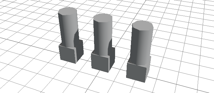
You can define complex geometries built with other components and reuse them multiple times in your scripts. And because these are merged into single geometries, the performance on the GPU should be really good. And the best part is that you can actually merge merged geometries to create really complex yet really performant models! Let's change our example one more time:
// a merger of a merged cube and a cylinder
$geo1 = startmerge();
box(1, 1, 1) > position(0, 0.5, 0);
cylinder(0.5, 0.5, 2, 8) > position(0, 2, 0);
endmerge();

$geo2 = startmerge();
usegeo($geo1) > position(-2, 0, 0);
usegeo($geo1);
usegeo($geo1) > position(2, 0, 0);
endmerge();

usegeo($geo2) > rotate(0, 0, 90) > position(0, 2.5, 0);
Render it now and take a look, we now have one single geometry that, using single objects or grouping alone, would actually be six geometries!
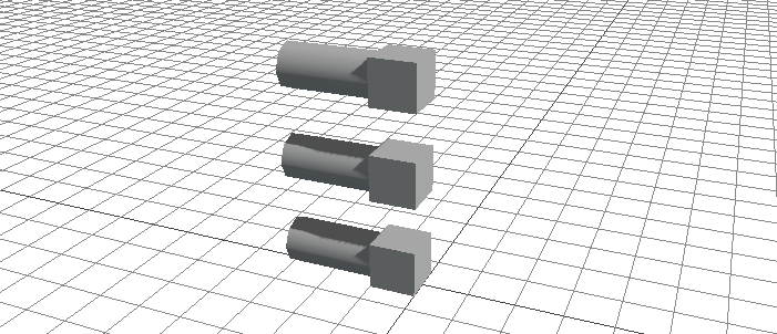
Of course, the more complex a merged geometry is, the larger the benefit to rendering performance.
So, you may be wondering, why would you ever use grouping instead of merging? Well, merging does have a drawback that is not present when using a group. Since all of the objects have been merged into one, they all share the same material.
We have not touched on materials yet, but you can think of the material as the "skin" for the object. To take a look, let's start with a basic cube again, and this time let's give it a basic skin.
// a basic cube
$box = box(1, 1, 1) > position(0, 0.5, 0);
$box > material(#ff0000);
Our cube is now a far prettier red color. Colors in Basic Modeler are specified using their hex code values.

Of course, you can also specify this in a one-line format:
// a basic cube
$box = box(1, 1, 1, #ff0000) > position(0, 0.5, 0);
Let's try again to create our merged geometry, but this time giving our box and cylinder their own color materials.
// a merged cube and a cylinder
$geo1 = startmerge();
box(1, 1, 1, #ff0000) > position(0, 0.5, 0);
cylinder(0.5, 0.5, 2, 8, #0000ff) > position(0, 2, 0);
endmerge();

usegeo($geo1);
Lame, even though we initialized both objects with their own colors, the object still shows up as a dull gray. This is because merging only works on the geometry level, no material properties are retained. If we want, we can apply a material to the entire merged geometry, like so:
// a merged cube and a cylinder
$geo1 = startmerge();
box(1, 1, 1) > position(0, 0.5, 0);
cylinder(0.5, 0.5, 2, 8) > position(0, 2, 0);
endmerge();
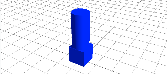
usegeo($geo1) > material(#0000ff);
If you render your script now, you will see a nice blue single geometry.
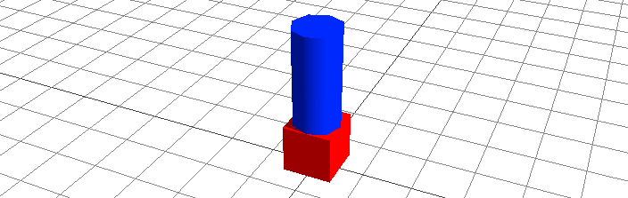
If we really want both objects to be their own color, we can attain that goal by using a group instead.
// a cube and a cylinder
$box = box(1, 1, 1, #ff0000) > position(0, 0.5, 0);
$pole = cylinder(0.5, 0.5, 2, 8, #0000ff) > position(0, 2, 0);

$group1 = empty();
$group1 > add($box);
$group1 > add($pole);
Now if you render the model, you will get the desired output, but at the expense of GPU performance.
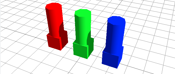
It is important to know when to use a group and when to create a merged geometry. If you have a lot of objects that all need to be the same color or texture, you will get far better performance using a merge. Merging also allows you to create multiple instances of the same basic shape. It's important to know that individual instances of a merged object can use different materials from each other. Let's go back to our earlier example, but this time assign some color to our geometry instances:
// a merged cube and a cylinder
$geo1 = startmerge();
box(1, 1, 1) > position(0, 0.5, 0);
cylinder(0.5, 0.5, 2, 8) > position(0, 2, 0);
endmerge();

$shape1 = usegeo($geo1) > position(-2, 0, 0) > material(#ff0000);
$shape2 = usegeo($geo1) > material(#00ff00);
$shape3 = usegeo($geo1) > position(2, 0, 0) > material(#0000ff);
Here we simply added material properties to each instance of our merged geometry, and this is the result:
Of course, materials can be used for a lot more than simple color adjustments, and you can read up on the full material function here.
Conclusion
By now you should have a basic understanding of what Basic Modeler is, what its syntax looks like, and how to create and manipulate basic objects. Play around with it and see what you can figure out! You can always take a look at the command references or go here to see what other tutorials are available. In the meantime, enjoy Basic Modeler, and happy modeling!